


Boring Machines
Showing all products from Group boring machines
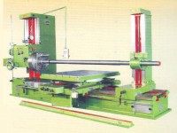
Horizontal Boring Machines
GURU NANAK Engineering Works(Regd.) with over 4 Decades' experience, have earned an enviable reputation as manufacturer of High Quality, Reliable & economical "KARAM" Highly Precision Horizontal Boring Machine which is a versatile Machine Tool for all types of roughing & finishing operations within the range of BORING, MILLING, DRILLING, REAMING & FACING. It is most suitable for machining bores in various types of Machine Bodies & Gear Boxes, for surface milling & especially for large dia flange facing. High precision workmanship, Sturdy & well proportionate design of Castings, High powered spindle & face plate drive along with Wide Range of Spindle Speeds & Gear Box Feeds ensure high production of accurately machined parts with the use of both H.S. Steel & Carbide tools. The Robust & Massive construction of the machine is a guarantee to withstand fully all the working stresses.
* The Casting is done with the mixture of 25% Steel & Ferro Chrome etc. to acquire proper Brinell Hardness & it is also seasoned for at least six months. The Machine is manufactured to Grade-1 Limits of ACCURACY.
* High Accuracy of machining due to precision scrapped/ground Guideways of Bed & Pillars etc.
* Fine Positioning by Dial Indicatiors & Verniers or Digital Read-Out System having an accuracy of .005 mm resolution for close manufacturing tolerances.
* Geometrical Accuracy of the machine conforms to Dr. SCHLESINGER'S ACCEPTANCE TEST CHART.
* Heavily ribbed box type Bed to withstand the Heavy Loads & Sturdy box type Columns to resist the heavy cutting force even at elevated height.
* Precise Synchronized Vertical Travel of Head Stock & Boring Stay Support.
* All traverses of X,Y & Z Axis of the machine as well as circular movement of the Work Table are
provided with automatic Feeds and Rapid Travels.
* All gears are precision cut on imported Mother Machinery to ensure smooth and Silent running.
* Manual Boring Head Height setting adjustment with a lever attached to feed gear box.
* Centralized control with swiveling Pendent Board for easy and convenient operations.
* Hand Operated knurled Knob attached to head stock drive motor and hand operated wheel attached to feed gear box motor for the safest engagement of speeds and feeds respectively.
* Special Attachments like Threading, Milling and Taper Boring Attachments permit to perform Multi-
Operations on a single machine.
* 4x90° Position of Rotary Table set with the help of an accurate adjustable stopper.
SAFETY CLUTCHES: To Disengage: ( a) Facing Mechanism (b) Sliding Mechanism of Cross Slide
(c) Rotary Movement of Work Table ( d) Longitudinal Movement of Work Spindle.
Apart from above safety Measures, Limit Switches & suitable Shear Pins are also provided for total safety of the machine
TECHNICAL SPECIFICATIONS
| SPECIFICATIONS | MM | MM | MM | MM | MM | MM |
| 1. Alloy Steel Work Spindle Handened & Ground-Diameter | 65 | 80 | 100 | 110 | 125 | 150 |
|
|
||||||
| 2. Morse Taper Number | 4 | 5 | 6 | 6 | 6 | Metric 80 |
|
|
||||||
| 3. Max. Longitudinal Movement of Working Spindle | 410 | 510 | 510 | 510 | 600 | 800 |
|
|
||||||
| 4. Number of Spindle Speeds | 9 | 9 | 9 | 9 | 9 | 9 |
|
|
||||||
| 5. Range of Spindle Speeds - R.P.M. | 20 to 300 | 15 to 300 | 15 to 300 | 15 to 250 | 15 to 250 | 15 to 250 |
|
|
||||||
|
6. Longitudinal Work Spindle Feeds (Nos.) |
9 | 9 | 9 | 9 | 9 | 9 |
|
|
||||||
|
7. Max. Height of the Spindle Axis from Table Surface |
800 | 925 | 1000 | 1100 | 1250 | 1500 |
|
|
||||||
|
8. Min. Height of the Spindle Axis from Table Surface |
20 | 25 | 35 | 35 | 35 | 50 |
|
|
||||||
| 9. Dimensions of the Rotary Table | 880x1050 | 900x1125 | 1030x1375 | 1100x1450 | 1225x1675 | 1500x2000 |
|
|
||||||
| 10. Longitudinal Table Traverse | 1500 | 1625 | 1775 | 1925 | 2050 | 2225 |
|
|
||||||
|
11. Long. Table Traverse Feeds ( Including one Rapid) |
10 | 10 | 10 | 10 | 15 | 15 |
|
|
||||||
|
12. Transversal Table Travel Feeds (Including one Rapid) |
10 | 10 | 10 | 10 | 15 | 15 |
|
|
||||||
|
13. Vertical Head Stock Travel Feeds (Including one Rapid) |
4 | 4 | 4 | 4 | 15 | 15 |
|
|
||||||
|
14. Rotary Table Autiomatic Feeds ( Including one Rapid) |
10 | 10 | 10 | 10 | 15 | 15 |
|
|
||||||
| 15. Max. Cross Movement of the Table | 910 | 1000 | 1100 | 1300 | 1550 | 2000 |
|
|
||||||
|
16. Max. Distance Between Stay Bearing and Facing Head |
2150 | 2400 | 2690 | 2800 | 2950 | 3400 |
|
|
||||||
| 17. Facing Head Diameter | 450 | 505 | 555 | 600 | 650 | 700 |
|
|
||||||
| 18. Weight Approximate in Kgs. | 7500 | 8500 | 10000 | 11500 | 16500 | 20000 |
STANDARD EQUIPMENTS :
Two Electric Motors :- 3 H.P.& 2 H.P. for 65mm H.B.M., 5 H.P. & 2 H.P. for 80mm H.B.M., 7.5 H.P. & 2 H.P. for 100mm H.B.M., 10 H.P. & 3 H.P. for 110mm H.B.M., 12.5 H.P. & 5 H.P. for 125mm H.B.M. & for 150mm H.B.M. 15 H.P. & 5 H.P. Electric Motors complete with Panel Board & Pendant Control Board. One Facing Head with Single Point Tool Holder, 2 Nos. Lubrication Pumps, 5 Nos. Limit Switches, One Steel Telescopic Cover to guard the machine Bed, One Machine Lamp, One Boring Bar, One Spindle Vibration Control Guide, Co-ordinate reading arrangement with Scales & Verniers for X,Y and Z Axis along with Crank Handles are also supplied as Standard Equipments with every machine.
EXTRA EQUIPMENTS :
2Axis or 3Axis Digital Read-out System for the Pin-Point Accuracy, Angular D.R.O. System for the perfect indexing of Rotary Work Table, TURCITE coating for the anti-friction movements of all major sliding parts of the machine, Vertical or Universal Milling Attachment, Taper Boring Attachment, Threading Attachment complete with special Threading Chuck, Revolving Centre with 6”/ 8” True Chuck, Three Nos. Dial Indicators in dust proof Aluminium housings with attachments & Electric Coolant Pump etc. can be supplied as EXTRA EQUIPMENTS at their Net Extra Costs.
Inquiry Details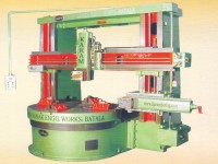
Vertical Turning Cum Boring Mills
TECHNICAL SPECIFICATIONS
| SPECIFICATION | UNIT | VTL-1 | VTL-1.2 | VTL-1.5 | VTL-2 | VTL-2.5 | VTL-3 |
| Table Diameter | mm | 1000 | 1200 | 1500 | 2000 |
2500 |
3000 | |
|
|
||||||||
| Max. Turning Dia | mm | 1200 | 1350 | 1750 | 2250 | 2750 | 3250 | |
|
|
||||||||
| Working Height Under Cross Rail | mm | 700 | 1000 | 1200 | 1500 | 1700 | 2000 | |
|
|
||||||||
| Ram Heads on Cross Rail | No. | One | One | One | One | One | One | |
|
|
||||||||
| Vertical Travel of Ram Head | mm | 450 | 550 | 650 | 750 | 800 | 900 | |
|
|
||||||||
| Swivel Angle of Ram Head | Deg. | +/-35 | +/-35 | +/-35 | +/-35 | +/-35 | +/-35 | |
|
|
||||||||
| Table Speeds | No. | 6 | 6 | 6 | 6 |
6 |
6 | |
|
|
||||||||
| Range of Table Speeds | RPM | 9 to 90 | 9 to 90 | 9 to 90 | 5 to 50 | 3 to 30 | 3 to 30 | |
|
|
||||||||
| Feeds for Horizontal & Vertical Travels | No. | 6 | 6 | 6 | 6 | 6 | 6 | |
|
|
||||||||
| Range of Feeds, Horizontal & Vertical | mm/min | 1.5 to 9 | 1.5 to 9 | 1.5 to 9 | 1.5 to 9 | 0.5 to 5 | 0.5 to 5 | |
|
|
||||||||
| Main Motor Drive | H.P. | 7.5 | 10 | 15 | 20 | 25 | 30 | |
|
|
||||||||
| Motor for Vertical Travel of Cross Rail | H.P. | 2 | 2 | 2 | 3 | 3 | 5 | |
|
|
||||||||
| Motor for Rapid Traverse | H.P. | 2 | 2 | 2 | 3 | 3 | 5 | |
1. The machine is complete with Full Electricals & duly equipped with Panel Board & Pendent Control Switch Board for the centralized control.
2. Gear Box for Auto-Feed Ram Head both Vertical & Horizontal is provided.
3. Alloy Steel duly hardened Gears are used.
4. Phosphorus Bronze Nuts are used for Lead Screws
5. 2.5mm Thick Turcite-B Lining is used on RAM/SADDLE.
6. Forced Lubrication with a Motorized Lubrication Pump is provided for the main Rotary Table. Independent Lubrication Pumps are provided for the Ram/Saddle & Cross Rail.
7. Precision Bearings and GUNMETAL guideways combination in the Bed/Table is provided to withstand Radial & Vertical Loads.
Inquiry Details

Horizontal Floor Boring Machines
We have developed "KARAM" High Precision Horizontal FLOOR TYPE BORING MACHINE which is most suitable for very heavy & High Volume Jobs which can't be accommodated on the work table of conventional Horizontal Boring Machine. Such jobs can easily be handled with the Floor Boring Machine as the work-piece is kept on the Floor Plate/s provided separately with the machine. Additional ROTARY TABLE Attachment is also supplied as per customer's requirement. The design of machine is unique which ultimately provides stiffness, accuracy, precision and optimum output. The especially designed machine bed is wide enough to provide a very rigid base to the moving column. The geometrical accuracy of the machine conforms to Dr. Schlesinger's Acceptance Test Chart. The special feature of this machine is that a Variable Frequency Drive (AC DRIVE) is used for the Centralized Control of Vertical Movement of Head Stock as well as Horizontal Movement of Saddle carrying column. These infinitely variable speeds are further controlled by a potentiometer duly fitting the same on pendant board of the machine which also eliminates shifting of levers again & again. Centralized Lubrication System ensures proper lubrication to all the moving parts. Special Attachments like Milling Attachment, Threading Attachment and Taper Boring Attachments enable the machine to perform multi-operations. CNC Version of the machine can also be offered as per requirement.
TECHNICAL SPECIFICATIONS
| SPECIFICATIONS | MM | MM | MM | MM |
| 1. Alloy Steel Work Spindle Hardened & Ground-Diameter | 100 | 110 | 125 | 150 |
|
|
||||
| 2. WORK SPINDLE TAPER |
M.T.6 or ISO 50 |
M.T.6 or ISO 50 |
M.T.6 or ISO 50 |
Metric 80 |
|
|
||||
| 3. Longitudinal Movement of the Working Spindle (Z – AXIS) | 600 | 700 | 800 | 1000 |
|
|
||||
| 4. Number of Spindle Speeds | 9 | 9 | 9 | 9 |
|
|
||||
| 5. Range of Spindle Speeds – R.P.M. | 15 to 250 | 15 to 250 | 15 to 250 | 15 to 250 |
|
|
||||
| 6. Vertical Travel of Head Stock (Y – AXIS) | 1 to 1.5 Mtrs. | 1 to 1.75 Mtrs | 1 to 2 Mtrs | 1.5 to 2.5 Mtrs. |
|
|
||||
| 7. Horizontal Traverse of Column (X – AXIS) | 2 to 8 Mtrs. | 2 to 8 Mtrs | 3 to 7 Mtrs. | 3 to 7 Mtrs. |
|
|
||||
| 8. Facing Head Diameter | 555 | 600 | 650 | 700 |
|
|
||||
| 9. Radial Traverse of Facing Slide (U-AXIS) | 150 | 150 | 180 | 200 |
|
|
||||
| 10. Main Spindle Motor | 7.5H.P. | 10 H.P. | 12.5H.P | 15 H.P. |
|
|
||||
| 11. Feed Gear Box Motor | 3H.P. | 3H.P. | 5 H.P. | 5 H.P. |
|
|
||||
| 12. Rotary Table Attachment (Optional) | 1000x1000 | 1250x1250 | 1500x1500 | 1500x2000 |
|
|
||||
| 13. Sliding Movement of Rotary Table | 800 | 900 | 1000 | 1250 |
|
|
||||
| 14. Floor Plate/s (Optional) |
1250x1250 x250 |
1500x1500 x250 |
2000x1500 x250 |
2000x2000 x250 |
Inquiry Details
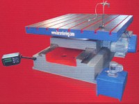
Rotary Linear Work Tables
We have developed "KARAM" High Precision Horizontal FLOOR TYPE BORING MACHINE which is most suitable for very heavy & High Volume Jobs which can't be accommodated on the work table of conventional Horizontal Boring Machine.
| ROTARY-LINEAR TABLE | KRLT-1 | KRLT-1.5 | KRLT-2 |
| Main Dimensions & Capacities : | ||||
|
|
||||
| Table Top – * Square | mm | 1000 x 1000 | 1500 x 1500 | 2000 x 2000 |
|
|
||||
| Number of T-Slots | nos. | 5 | 6 | 7 |
|
|
||||
| Size of T – Slots | mm | 19 | 19 | 19 |
|
|
||||
| Load Carry Capacity | Kgs. | 4000 | 6000 | 10000 |
|
|
||||
| Total Height, incl. Rotary Table | mm | 750 | 750 | 800 |
|
|
||||
| Number of Guideways | nos. | 2 | 2 | 3 |
|
|
||||
| Traverse : | ||||
|
|
||||
| *Sliding movement of Work Table | mm | 1000 | 1200 | 1500 |
|
|
||||
| Drive Data : | ||||
|
|
||||
| Electric Motor | H.P. | 3 | 5 | 7.5 |
|
|
||||
| A.C. Drive | H.P. | 3 | 5 | 7.5 |
|
|
||||
| Linear Feed Rate with A.C. Drive | mm/min | 50 to 500 | 50 to 500 | 50 to 500 |
|
|
||||
| Rotary Movement for Positioning | With Power Feed | Yes | Yes | Yes |
|
|
||||
| Accuracy : | ||||
|
|
||||
| Positioning Accuracy | With D.R.O. | +/- 1 Minute | +/- 1 Minute | +/- 1 Minute |
|
|
||||
| Positioning Accuracy Linear Axis | mm | 0.02 | 0.02 | 0.02 |
Inquiry Details
Ashoktools Corporation
Ashok Bhavsar
12 Devdarshan Complex,GIDC Vatva Road,, Ahmedabad-382445
Gujarat (India)
Contact Us
Phone +91(79-25832167)
Mobile +91(9825033734) / (9426301306)
 |
info@ashoktools.com |


